Date: November 30, 2023
Content: Article originally posted on the Fast Radius Website
Bonus: Downloadable PDF available on Fast Radius Website
Multi Jet Fusion enables the efficient production of end-use nylon parts using additive technologies. Here’s a checklist for design teams.
Introduction
What is Multi Jet Fusion?
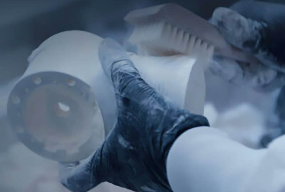
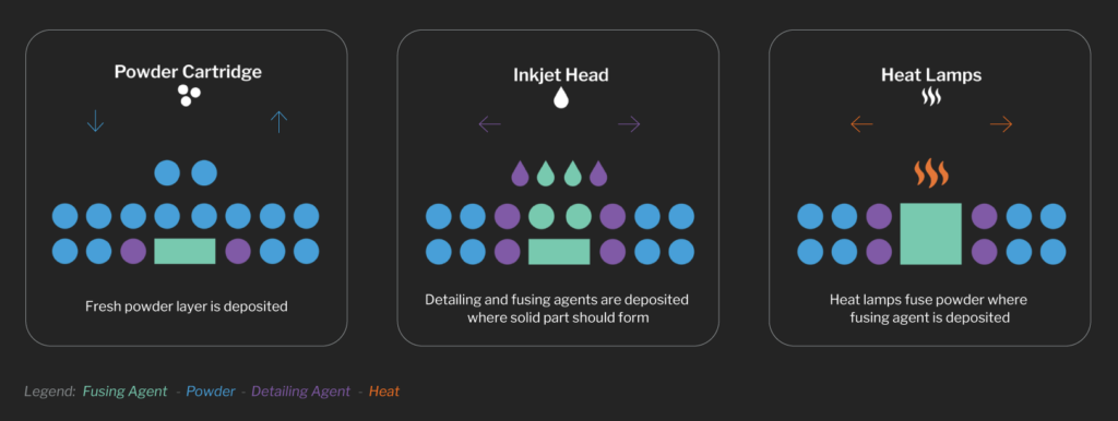
Multi Jet Fusion (MJF) is an industrial form of 3D printing that can be used to produce functional nylon prototypes to higher volume production parts with exceptional design freedom and mechanical properties. The MJF process works by using inkjet nozzles to selectively distribute fusing and detailing agents across a bed layered with nylon powder. Unlike selective laser sintering, which uses lasers to fuse the powder into solid material, the MJF printer uses a continuous sweeping motion to distribute agents and apply heat across the print bed layer by layer until the part is finished, MJF can produce high-quality parts at high speeds.
This manufacturing process also does not require support structures to produce parts, making it possible to create complex geometries like internal channels or co-printed assemblies. MJF parts have mechanical properties comparable to injection-molded ones, but without the need for expensive tooling.
Designing for manufacturability will go a long way in ensuring optimal part quality and yield, minimizing post-processing needs, and driving cost reductions. Here’s a quick checklist to help your team ensure that you’re following MJF design best practices.
1. Is MJF a suitable process for my project?
Before diving into design changes, it is important to ensure that the MJF process will meet all product requirements. Here are a few questions to ask yourself:
Do any of the material offerings meet my product requirements?
While MJF has many strengths, it has a limited list of approved materials. PA12 and its glass bead counterpart are fairly versatile for rigid plastic applications. TPU, a flexible polyamide, can find use where an elastomeric material is required. If the available materials do not meet a specific requirement, you may need to consider a different process.
Does my part fit in the build volume?
One key limiting factor is the machine’s build volume, which is 380 x 380 x 284mm for the Jet Fusion 4200. In some cases, large parts can be printed as smaller subcomponents and assembled using adhesive or mechanical joints. In this case, design features such as dovetail joints may facilitate alignment and adhesion.
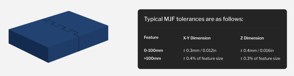
Do I have any tight tolerances I need to hit?
While the gap between additive and injection molding tolerances is narrowing, it is important to make sure that MJF’s tolerances are sufficient within the context of your assembly.
Example of dovetail joint used to adhere subcomponents
2. Are there areas where I can use less material?
In most cases, MJF defects are caused by thermal gradients that develop during the build. If the material cools unevenly, the piece may warp or develop sinks. Parts that are long and thin, have abrupt changes in cross-sections, or have thin curved surfaces are especially prone to shrink-induced warp.
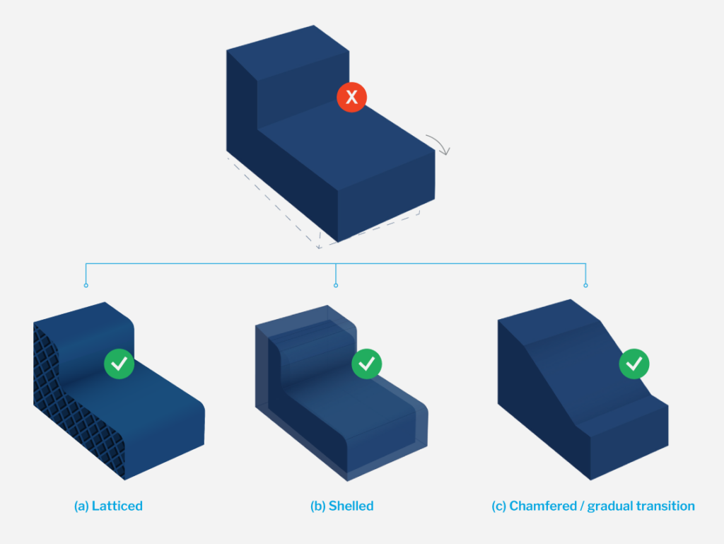
Removing material from part designs wherever possible through the use of pockets, shelling, lattices, and topology optimization is key to mitigating and preventing these defects. Avoiding large changes in cross-sections is another way to limit warp. Ensure that chamfers and fillets are incorporated where needed throughout the part design to make the transitions between different features more gradual.
3. Are my features above the minimum threshold size?
In general, the wall thickness of MJF-printed parts should be a minimum of 1.5mm. Small design features should also be no smaller than 1.5mm, though some features such as slits, embossing, engraving, or the diameters of holes and shafts can be as small as 0.5mm. For embossed or debossed text, the font should be no smaller than 6pt (approximately 2mm) and should be a minimum of 0.3mm deep.
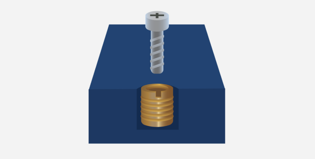
If a part includes screw threads, they should be M6 or larger. Where smaller, more precise, or more durable threads are needed, consider using threaded inserts. Beyond feature resolution, you should also consider how small, slender features might break off in post-processing.
4. Have I taken assembly tolerances into account?
Even with the greater geometric flexibility provided by the MJF process, some applications may still require a part to be assembled from multiple components. In general, mating faces should have 0.4 – 0.6mm of clearance to ensure that the components can properly fit.